
Precision Probing for Resistance Measurement and Continuity Testing of Micro-Scale Electronic Features
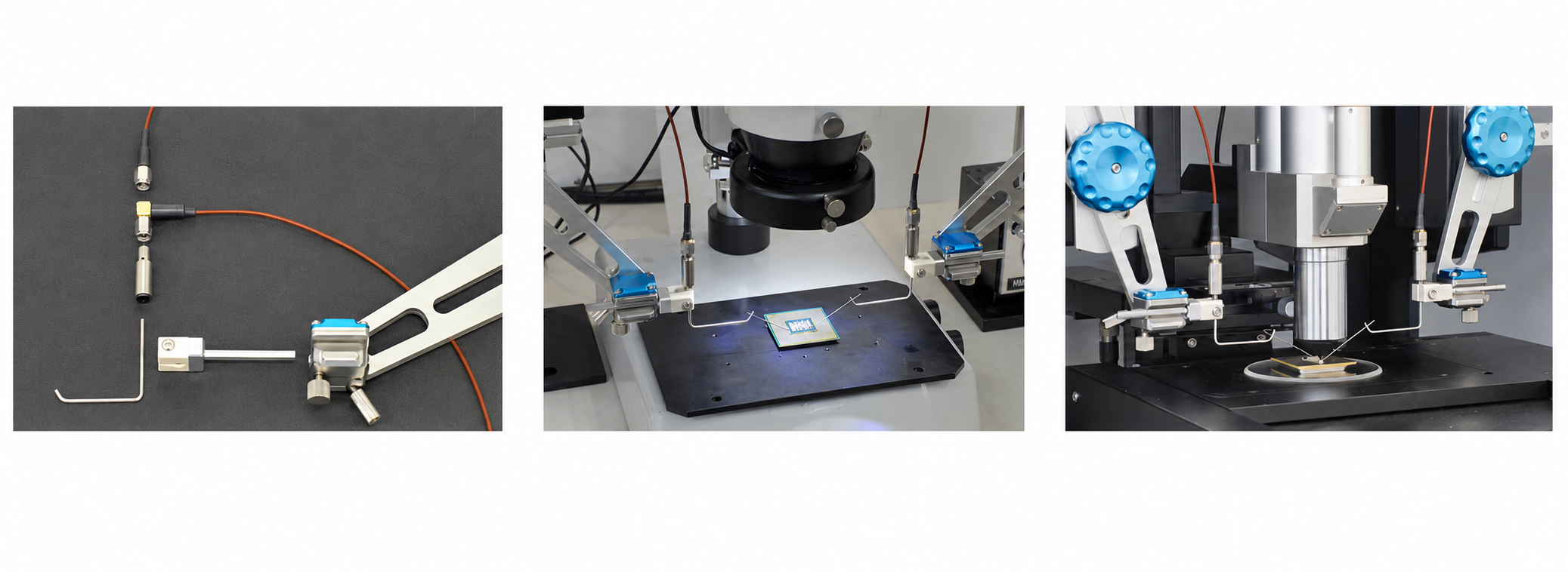
Resistance measurement and continuity testing are widely used to evaluate electrical performance, verify circuit integrity, and identify defects in electronic devices and materials. As electronic devices continue to become smaller and more complex, performing these measurements becomes increasingly challenging. Semiconductor devices, printed circuit boards, microelectrodes, sensors, thin-film structures, and other miniature electronic features often contain conductive areas that are difficult to access using conventional testing methods.
Reliable electrical measurements depend on more than the measurement instrument itself. Accurate resistance measurement and continuity testing require stable probe positioning and reliable electrical contact throughout the testing process. Even slight shifts in probe position can result in fluctuating readings, measurement uncertainty, and reduced confidence in analytical results.
To address these challenges, researchers and engineers use precision electrode holders to support micro-scale probing applications. By helping maintain stable probe positioning and reliable electrical contact during testing and analysis, electrode holders support accurate resistance measurement, continuity testing, and electrical inspection of small electronic features. This post examines the challenges associated with micro-scale electrical inspection and explains how precision electrode holders support accurate resistance measurement, continuity testing, and reliable electrical inspection of miniature electronic features.
Why Micro-Scale Electrical Inspection Is Challenging
Electrical inspection becomes increasingly difficult as electronic features continue to shrink in size. While electrical measurement principles remain the same, accessing and testing these miniature structures requires a much higher degree of precision than conventional inspection methods. Several factors make micro-scale electrical inspection particularly challenging, including:
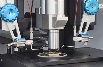
- Shrinking Conductor Widths and Contact Pads: Advanced electronic devices often incorporate extremely fine conductive traces, interconnects, and contact pads that provide limited surface area for probe placement, making reliable electrical contact more difficult to achieve.
- Limited Access to Test Locations: Densely packed components, multilayer structures, and closely spaced conductive features can restrict physical access to measurement points, increasing the complexity of probe positioning during inspection.
- Difficulty Maintaining Consistent Probe Contact: Small test areas require precise alignment and controlled contact force. Even minor variations in probe placement can affect contact quality and influence measurement stability.
- Risk of Damage to Delicate Structures: Thin conductive traces, microelectrodes, and miniature electronic features can be susceptible to damage if excessive force or improper probing techniques are applied during testing.
- Measurement Variability due to Probe Movement: Unstable probe positioning can introduce fluctuating resistance values, inconsistent continuity results, and reduced measurement repeatability, making it more difficult to obtain reliable inspection data.
Understanding Resistance Measurement and Continuity Testing
Resistance measurement and continuity testing provide critical information about the electrical condition of miniature electronic features. Let us understand how each technique contributes to electrical inspection, troubleshooting, quality assurance, and materials characterization.
Resistance Measurement
Resistance measurement determines the opposition to electrical current flow within a conductor, component, or electrical pathway. The measurement helps evaluate electrical performance and identify conditions that may affect circuit functionality.
Key applications include:
- Verifying Electrical Performance: Resistance measurements help confirm that conductors, interconnects, and electrical components perform within expected operating parameters.
- Identifying Potential Defects: Resistance measurements help identify contamination, material degradation, poor electrical connections, manufacturing defects, and damaged conductive pathways that may affect performance.
- Supporting Material and Device Characterization: Researchers use resistance measurements to evaluate conductive materials, thin films, microelectrodes, and electronic structures during development and analysis.
Continuity Testing
Continuity testing verifies whether an electrical pathway remains complete between two points within a circuit or device. The test is commonly used to confirm electrical connectivity and identify interruptions in conductive paths.
Key applications include:
- Confirming Electrical Connections: Continuity testing verifies that electrical pathways remain connected and capable of carrying current between designated points.
- Detecting Open Circuits and Broken Conductors: The technique helps identify damaged traces, broken interconnects, failed solder joints, and disconnected electrical pathways.
- Supporting Troubleshooting and Quality Assurance: Engineers and technicians use continuity testing during manufacturing, inspection, maintenance, and failure analysis to verify circuit integrity and locate electrical faults.
Why Stable Probe Contact Matters
At micro scale, the quality of the probe-to-sample interface can directly influence measurement results. Small conductive features provide limited contact area, making electrical measurements more sensitive to variations in probe placement and contact conditions.
The following factors highlight why stable probe contact is essential during resistance measurement, continuity testing, and electrical inspection:
- Contact Resistance Can Influence Results: Unstable or inconsistent contact may introduce additional resistance at the probe interface, affecting measured values and reducing confidence in the data.
- Intermittent Contact Can Produce False Readings: Temporary loss of electrical contact may generate fluctuating resistance values or inconsistent continuity test results that do not accurately represent the condition of the test feature.
- Small Variations Can Affect Measurement Consistency: Minor changes in probe placement, contact angle, or contact pressure can alter the probe-to-sample interface, potentially affecting measurement consistency across repeated tests.
- Repeated Measurements Require Consistent Contact Conditions: Comparative testing, failure analysis, and research applications often involve multiple measurements at different locations. Consistent contact conditions help ensure meaningful comparison between measurement results.
Electrode Holders for Precision Probing
Electrode holders available in macro, micro, and micro high-conductivity types are used to support precision probing during resistance measurement, continuity testing, and localized electrical inspection of micro-scale features. They provide a controlled method for positioning probes on specific test locations that may be difficult to access using manual probing techniques alone.
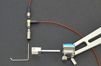
These systems are commonly used for electrical evaluation of:
- Electronic components
- Circuit board traces
- Microelectrodes
- Thin-film structures
- Fine conductive patterns
- Microfabricated electronic features
Here are several ways electrode holders contribute to effective micro-scale testing and analysis:
- Support Accurate Probe Positioning: Electrode holders allow researchers and engineers to accurately position and maintain probes on specific conductive features, helping ensure controlled probe placement throughout the measurement process.
- Enable Measurements on Small and Difficult-to-Reach Features: Fine positioning capabilities allow probes to access narrow conductive traces, small contact pads, microelectrodes, thin-film structures, and other miniature features that may be difficult to evaluate using conventional handheld probing methods.
- Facilitate Localized Electrical Measurements: Electrode holders enable electrical evaluation of individual conductive regions without unnecessarily contacting adjacent structures, making them suitable for inspecting densely packed electronic features.
- Support Systematic Inspection Across Multiple Test Locations: Electrode holders simplify probe repositioning between measurement points, allowing operators to follow a consistent inspection procedure across multiple locations on the same sample or device.
- Improve Measurement Confidence: Consistent probe positioning allows researchers and engineers to evaluate measurement results with greater confidence, particularly when comparing data collected from multiple inspection points or repeated test cycles.
- Reduce Setup Time During Measurements: Fine adjustment mechanisms simplify probe alignment and minimize repeated manual corrections, allowing operators to prepare for electrical measurements more efficiently.
- Improve Overall Inspection Efficiency: Streamlined probe positioning and consistent inspection procedures help laboratories and research facilities perform electrical evaluation more efficiently, particularly when processing multiple samples or conducting repetitive testing.
How a Precision Probing Workflow Works
A precision probing workflow combines microscopic observation, controlled probe positioning, and electrical measurement techniques to evaluate small conductive features. While specific procedures vary depending on the application and instrumentation, the process generally follows a series of common steps.
- Identifying the Target Location Under a Microscope: The operator first locates the conductive feature or measurement point using an optical microscope. Direct visual observation helps ensure accurate targeting of small structures and test locations.
- Positioning the Electrode Holder Above the Test Area: The electrode holder is adjusted to bring the probe into the vicinity of the selected measurement location while maintaining clear visibility of the target feature.
- Aligning the Tungsten Probe with the Desired Feature: Using fine positioning controls, the operator aligns the tungsten probe with the conductive trace, contact pad, microelectrode, or other structure being evaluated.
- Establishing Electrical Contact with the Test Point: The probe is carefully brought into contact with the target location. Controlled positioning helps achieve the desired contact while minimizing disturbance to the surrounding structure.
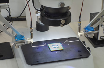
5. Performing the Required Measurement: Once contact is established, resistance measurements, continuity tests, or other electrical evaluations can be performed using the appropriate measurement instrument.
6. Recording and Analyzing the Results: Measurement data is collected and reviewed to evaluate electrical performance, verify connectivity, identify abnormalities, or support further research and failure analysis activities.
Capabilities of Electrode Holders
Electrode holders incorporate several features that support controlled probing and electrical analysis of miniature conductive structures.
- Accommodate Different Probe Types: Many electrode holders can be used with tungsten probes and other specialized probing tools, allowing users to select probe configurations appropriate for the application.
- Enable Fine Mechanical Adjustments: Precision adjustment mechanisms allow incremental movement during probe setup and alignment, helping users approach small test locations with greater control.
- Enable Multi-Directional Positioning: Electrode holders can be adjusted across multiple axes, allowing probes to be positioned at different locations, orientations, and approach angles.
- Accomodate Various Sample Geometries: Electrode holders can be used when inspecting flat surfaces, raised structures, patterned substrates, and other sample configurations encountered in research and analysis.
- Support Repetitive Inspection Workflows: Once configured, electrode holders can be used across multiple measurement locations and samples, supporting structured testing procedures and comparative analysis.
- Integrate Within Existing Laboratory Setups: Electrode holders can be incorporated into microscope-based inspection environments and used alongside electrical measurement instruments commonly found in research and analytical laboratories.
Applications and Use Cases of Electrode Holders
Engineers use electrode holders to perform electrical evaluation of individual electronic components during development, manufacturing, and quality inspection. Here are some common applications:
- Electronic Component Testing: Electronic components often contain compact terminals and fine conductive regions that require controlled probe placement during electrical evaluation. Here are some common applications of electrode holders.
- Verification of Electrical Connections
- Component Performance Evaluation
- Printed Circuit Board Inspection: Advanced printed circuit boards incorporate dense layouts with fine traces and closely spaced contact pads. Electrode holders enable accurate access to specific measurement locations without disturbing adjacent features.
Key applications include:
- Trace Continuity Verification
- Circuit Troubleshooting
- Microelectrode Testing: Microelectrodes are widely used in biomedical research, electrochemical analysis, sensor development, and materials science. Their small dimensions require stable probe positioning during electrical evaluation. Key applications of the holders include:
- Electrical Characterization
- Contact Verification
- Failure Analysis: Failure analysis often requires electrical measurements at specific locations within damaged or malfunctioning devices. Electrode holders provide controlled access to these areas during investigative workflows. Key applications include:
- Detection of Open Circuits
- Investigation of Electrical Faults and Defects
Best Practices for Electrical Inspection Using Electrode Holders
Proper setup and operation of electrode holders contribute to consistent electrical measurements and efficient inspection workflows. Following established practices can help improve measurement quality, protect delicate electronic features, and maintain reliable performance during resistance measurement and continuity testing. Here are some recommended practices:
- Use Appropriate Microscope Magnification: Select a microscope magnification that provides a clear view of both the probe tip and the target feature. Good visibility allows operators to accurately position the electrode holder before establishing electrical contact.
- Verify Probe Alignment Before Testing: Confirm that the probe is properly aligned with the intended measurement location before performing resistance measurement or continuity testing. Accurate alignment helps ensure that the probe contacts the desired feature without interfering with adjacent conductive structures.
- Apply Minimal Force When Contacting the Sample: Lower the probe gradually using the electrode holder and apply only the amount of force required to establish electrical contact. Excessive force may damage delicate conductive traces, contact pads, microelectrodes, or thin-film structures.
- Maintain a Stable, Vibration-Free Work Environment: Position the electrode holder on a stable microscope stage or work platform and minimize external vibration during testing. A stable setup helps maintain consistent probe positioning throughout the measurement process.
- Inspect Probe Condition Regularly: Inspect the probe before mounting it in the electrode holder and periodically during use. Replace probes that show signs of wear, bending, contamination, or tip damage to maintain consistent measurement performance and reliable electrical contact.
Common Challenges and Solutions When Using Electrode Holders
Proper setup and adjustment of electrode holders contribute to accurate and consistent electrical measurements. During electrical inspection, operators may encounter practical challenges that affect probe positioning and measurement quality. Here are some common challenges and their corresponding solutions:
| Challenge | Solution |
| Difficulty positioning the probe on the intended measurement location | Use the electrode holder’s fine adjustment controls together with appropriate microscope magnification to accurately position the probe. |
| Probe misalignment during setup | Verify probe alignment before establishing electrical contact and make incremental adjustments using the electrode holder. |
| Unintended movement during measurement | Ensure the electrode holder is securely mounted and tighten adjustment mechanisms before performing measurements. |
| Inconsistent results between repeated inspections | Maintain a consistent electrode holder configuration and follow the same positioning procedure for each measurement. |
| Reduced measurement quality due to a worn or damaged probe | Inspect the probe before mounting it in the electrode holder and replace it when signs of wear, bending, or contamination are observed. |
Instrumentation for Electrical Inspection Workflows
Successful electrical inspection of micro-scale electronic features relies on the coordinated use of several precision instruments other than just electrode holders. Each component contributes to a specific stage of the inspection process, from probe positioning and visual observation to electrical measurement and data collection. Here are the primary instruments commonly used in these workflows:
- Tungsten Probes: Tungsten probes provide the fine tip geometry required to contact small conductive traces, contact pads, microelectrodes, and other miniature electronic structures during electrical evaluation.
- Precision Positioning Systems: Multi-axis positioning systems enable controlled movement and fine adjustment of probes, allowing accurate alignment with closely spaced measurement locations.
- Optical Microscope Systems: Optical microscopes provide the magnification needed to locate target features, monitor probe placement, and observe the probe-to-sample interface throughout the inspection process.
- Resistance Measurement Instruments: Digital multimeters, source measure units (SMUs), and other resistance measurement instruments typically already present in the customer’s lab are connected via the precision probes and electrode holders to evaluate electrical resistance during research, inspection, and quality verification.
- Continuity Testing Equipment: Continuity testers, connected through the positioned probes, verify electrical connectivity between designated test points and support circuit verification, troubleshooting, and fault localization.
Advance Your Electrical Inspection with Barnett Technical Services
As electronic devices continue to incorporate smaller and more intricate conductive features, accurate resistance measurement and continuity testing require precise probe positioning and consistent electrical contact. Precision electrode holders play an important role in supporting reliable electrical inspection by enabling controlled probing of miniature electronic features across research, semiconductor analysis, materials science, and failure investigation.
Barnett Technical Services provides integrated electrical inspection and micro-probing solutions, including precision electrode holders, tungsten probes, and complementary inspection equipment for advanced testing applications. Whether you are developing new electronic devices, investigating electrical faults, or performing routine quality inspection, our team can help you identify the right solution for your measurement and analysis requirements.